CNC MINI and L293D Shield arduino


Hi friends,I'am AIT-LASRI YOUNES
In this project we will talk about making corrupted DVD and cd-rom drives recycled and producing cnc at low cost. Let's start building the mini cnc project that draws

Step 1: Materials

  1. Arduino (can be nano, uno or mega)
  2. Damaged DVD or CD-ROM (the stepper motor inside will be running)
  3. 2 pieces of damaged dvd or cd-rom (the stepper motor inside will be running)
  4. Servo motor (Mg90 is enough)5v 2
  5. amp battery or adapter
  6. Plexi plate with 20 x 16 cm and 5 mm thickness to hold the X axis.
  7. Plexi plate 15 x 16 cm and thickness 5 mm to secure the Y axis
  8. You can use a plexi plate of 75 × 75 mm and a thickness of 5 mm for the drawing surface.
  9. 1 piece M5 bolt nut (to fix the plate)
  10. 14 pieces M4 bolt nut

Step 2: Front and rear overview of the mini cnc and explanations 

Front and rear overview of the mini cnc and explanations !

  1. X plane Plexi Plate (200x150x3 mm)
  2. Y plane Plexi Plate (200x150x3 mm)
  3. X-axis movement mechanism (dvd drive yard mechanism)
  4. Y-axis movement mechanism (dvd drive yard mechanism)
  5. Z plane section
  6. Servo-motor
  7. Pen Holder
  8. Pen fixing nut - screw arrangement (1 piece M5 bolt nut)
  9. Pen
  10. Drawing table (75x75x5 mm plexi plate)
  11. Axis supports and screw nuts
  12. Stepping motor for X-axis motion
  13. Stepping motor for Y-axis movement
  14. Paper clips to secure the paper
  15. 14 pieces M4 bolt nut
  16. Pen holder support
  17. Z-axis
  18. Cables4
  19. Angles
  20. The control unit (Arduino uno, 2 l239d, pertinaks, energy input jack)
  21. Usb cable for computer connection

Step 3: Mechanical part

We will use the part with the mechanical part DVD or the rail system inside the Cd-R0m drive.In this section the stepper motor is connected to the worm screw shaft and moves the part of the laser reader which is connected to the shaft by turning the shaft. We are removing this part without harm. In the same way, the other driver is also dismantled and a total of two stepper motor systems are installed. If you use DVD-Rom, you can also make laser cutter with its laser diodes. These are the mechanical parts that move the axes. We will extract other mechanical parts from the 3d printer.
You can download parts stl files here >>here (ici)

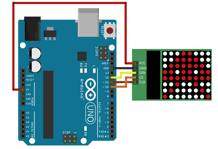
Step 4: Electronic Section

Electronic Section

In our electronic system we will connect the two stepper motors which will move the x and y axis and one servo motor which will lift and lower the die.

Step 5: Arduino Code Part

download  here :  code.txt

Step 6: Processing Code

download here :  code 2.txt

Step 7: INKSCAPE SETTINGS

To get gccode output with INKSCAPE, first download the makerbot unicorn G-code plugin here >> Inkscape gcode plugin
İnkscape full setting and details of the project >> Arduino cnc project

Step 7: INKSCAPE SETTINGS

To get gccode output with INKSCAPE, first download the makerbot unicorn G-code plugin here >> Inkscape gcode plugin
İnkscape full setting and details of the project >> Arduino cnc project

Matrice des LED 8X8 avec Arduino

Objectifs et analyse de fonctionnement 

Le projet consiste la gestion d’une matrice des LED 8X8 à base d’Arduino en utilisant le circuit MAX7219CNG. Le projet électronique utilise une libraire pour la gestion du circuit MAX7219CNG avec une liaison SPI. Ce mini projet mis en évidence l’utilisation de la libraire avec d’autres fonctions secondaires (décalage, conversion, …).

Fonctionnement de la matrice des LEDs 8×8

Projet électronique  Gestion d'une matrice des LED avec Arduino - matrice led
La matrice des LED est constituée de 8 lignes et 8 colonnes. On peut assimiler la matrice à un tableau 1D de 8 éléments, chaque élément du tableau est codé sur 8 bits Ex B00001111 ou 0x0F, dans la figure ci-dessous illustre le passage d’une matrice 8×8 à un tableau sur 8 éléments de type Bye ou Unsigned char. On verra dans la suite la fonction qui permet d’afficher le code dans la matrice 8×8.
Le module utilisé est basé sur MAX7219 avec une liaison série pour les données. Le bus SPI est constitué de trois fils :
  • CS : Chip Select pour l’activation du modèle
  • CLK : l’horloge synchrone pour les données. L’horloge définie la vitesse de transmission des données série
  • DIN : La donnée série sur 8 bits
Plus des détails sur la transmission série : SPI 
Projet électronique  Gestion d'une matrice des LED avec Arduino - Matrice fonctionnement

Lien vers une Application gratuite de gestion d’une matrice 8×8 des LED

Commentaires sur le programme

  • void int2BitArray(unsigned char dataIn,unsigned char taille, byte *dataArray)
La fonction int2BitArray permet de convertir une variable char en un tableau sur N bits (N=8 bits)
Ex1 : pour dataIn=10, taille=8 alors la variable de sortie dataArray[8]={0,0,0,0,1,0,1,0]
         ( équivalant à B00001010)
Ex2 : dataIn=127, taille=8 alors la variable de sortie dataArray[8]={0,1,1,1,1,1,1,1]
         ( équivalant à B011111111)
  • void DataShiftArray(unsigned char NumShift,unsigned char taille, byte *DataIn, byte *DataOutShift)
La fonction DataShiftArray permet de décaler à droit un tableau de longueur « taille » de bits (tableau binaire) DataIn, le résultat est stocké puis retourné dans le tableau DataOutShift. Au début le tableau DataOutShift est supposé initialisé à 0.
Ex : NumShift=3, taille = 8, DataIn[8]={1,1,1,1,0,0,0,0} alors DataOutShift[8]={0,0,0,1,1,1,1,0}.
L’objectif de la fonction est de décaler un objet dans la matrice 8×8 des LED.

Assemblage en cascade des matrices

Chaque matrice est définie par sont indice, la première à l’indice 0, la deuxième 1 … Pour ecrire dans une matrice il suffit de préciser l’indice de la matrice :)
Projet électronique  Gestion d'une matrice des LED avec Arduino

Les fonctions disponibles dans la libraire 8*8

Projet électronique  Gestion d'une matrice des LED avec Arduino - photos projet (7)
Projet électronique  Gestion d'une matrice des LED avec Arduino - photos projet (6)
Projet électronique  Gestion d'une matrice des LED avec Arduino - photos projet (4)
Projet électronique  Gestion d'une matrice des LED avec Arduino - photos projet (3)
Projet électronique  Gestion d'une matrice des LED avec Arduino - photos projet (1)

Un petit commentaire de vous, un Grand encouragement pour nous :)

- Bon Courage –

Traffic light 4 way. Using arduino uno


This is a simple 4-way Traffic Light Controller that I made. The LEDs are controlled my an arduino uno.
1. 4 red led, 4 yellow led, 4 green led
2. Breadboard
3. Arduino UNO
4. Cable

Step 1:


Step 2: code here


Control Brushless Motor using Arduino


Ever thought of controlling a ESC a.k.a Electronic Speed Controller of a Brushless Motor without a Transmitter and Receiver or have a Project in which you want to control a Speed of Brushless Motor using a simple Circuit or Arduino ,then there is a way we can do it with Arduino Microcontroller.This involves the use of PWM signal from arduino to control the speed of brushless motor with a ESC.This will save you the money to buy a servo tester or a RC Transmitter and receiver.So Lets Get started!!
Things you need:
  1. Arduino(I will be using a UNO)
  2. Potentiometer
  3. Lipo Battery(Which is able to supply Sufficient Current)
  4. ESC(Make sure that the motor draws less current than mentioned on the ESC)
  5. Brushless Motor(In my case a A2212)

Step 1: ​Wiring up the Circuit

​Wiring up the Circuit
$_12.JPG4643704393_7e12bc65e2_o.jpg

qqqq.PNGDSCN2902.JPG

First connect the three terminals of Brushless motor to the the three terminals of the ESC.Screw the Motor to a heavy wooden plank anything similar so that it remains stable at high RPM.Download and Flash the code available at the bottom of the page to the arduino using a usb cable(Code is explained in the further part of this page). Connect the signal wire of ESC mostly white or yellow colour to any PWM pin Arduino,I connected it to the D8 pin and specified it a Pin 8 in the Arduino Sketch.You can use more than one pins for controlling many motors.
Connect the Potentiometer to the vcc or 5v pin of the Arduino and the Ground.
Connect the third terminal that is the variable pin to the Analog pin A0 You can power the Arduino using the BEC(Battery Eliminator Circuit)Present in your ESC.To use the BEC just connect the red thick wire to the Vin Pin of Arduino .It can provide 5V.Not all ESC's have a BEC,in this case you can use a external 5v power supply.After Powering the Arduino now connect the Lipo battery to your ESC.
You are Done!!Now slowly turn the Potentiometer Knob to start and increase the speed of the Motor.

Step 2: ​Arduino Code

In this code we are simply mapping or refering the maximum(1023) and minimum(0) Analog values at pin A0 to the required maximum(2000) and minimum(1000) values to operate and control the speed of the ESC.You may require to change the max an min values of the ESC i.e 1000 and 2000 to different values in other words you may need to caliberate it,Because Diffrent ESC's may have diffrent start point and end point.
For more tutorials visit-RZtronics

Code
#include //Using servo library to control ESC
Servo esc; //Creating a servo class with name as esc
void setup()
{
esc.attach(9); //Specify the esc signal pin,Here as D8
esc.writeMicroseconds(1000); //initialize the signal to 1000
Serial.begin(9600);
}
void loop()
{
int val; //Creating a variable val
val= analogRead(A0); //Read input from analog pin a0 and store in val
val= map(val, 0, 1023,1000,2000); //mapping val to minimum and maximum(Change if needed) esc.writeMicroseconds(val); //using val as the signal to esc
}

Arm. Building the Robotic Arm with 3DP +Arduino


This is a 5 axis Robotic Arm ,I made it with 3D Printer & Arduino .
You can follow bellow steps to download the resource and make it.
Preparing Stuff:
1.MG995 servo x 5
2. SONY Joystick x1
3. Arduino x1.

Step 1: See The Demo Film

You can see the Demo Film.Using Joystick to control Robotic Arm.

Step 2: Download the elements.

You can download Robotic elements from below website:http://www.thingiverse.com/thing:994180

Step 3: Assemble Robotic Arm

please sse the below website show how to assemble it.http://arbu00.blogspot.tw/2015/09/how-to-build-robotic-arm-made-by-3dp.html

Step 4: Connecting Arduino.

please see below website to show how to connect Arduino H/W.http://arbu00.blogspot.tw/2015/07/arduino-5.html

Step 5: Arduino sample code

You can download the RobotArm03.ino .It support 2 kind of controlled modes.One is auto mode,another is manual mode.controlling Robotic Arm by one Joystick .


Installation of Bluetooth Multi-Function Smart Car for Arduino Controlled


图片2.jpg

So you want to make a smart car? Don't know where to start? How about learning with ICStation team.

The Arduino Bluetooth Smart Car has the function of Complete tracking, obstacle avoidance, infrared remote control and Bluetooth remote control. It is a MCU study and application development system base on Atmege328.The greatest feature is that you can control it with Mobile phone bluetooth of Android system. That’s may have a lot of fun.To make it, you need a number of kits which contain a number of interesting programs, and expand external circuit module to implement functions.
So now let's begin to build this smart car.

Major Parameter:
  1>.Motor parameter:
        Power apply:6V-9V;
        Reduction gear ratio:1:48;
  2>.Selection L298N module driver motor,segregate form CPU.
  3>.Three tracking modules,detection white and black line.Available with fall prevention control.
  4>.Infrared remote communication module,composition of remote control system of smart car.
  5>.Bluetooth wireless module,can match with mobile phone to control smart car.
  6>.Input voltage 7V-12V,can connect to different kinds of sensor.The more sensors ,the more functions.
  
Components:
  1>.stepper motor  x4
  2>.wheel  x4
  3>.motor fixed block  x4
  4>.100x213x5mm perspex sheet  x1
  5>.100x213x5mm perspex sheet  x1
  6>.L298N driver board  x1
  7>.Arduino uno 328 controller  x1
  8>.Arduino sensor shield V5  x1
  9>.PTZ  x1
  10>.Servo motor  x1
  11>.Ultrasonic module  x1
  12>.Three channel tracking module  x1
  13>.Infrared receive sensor  x1
  14>.Transducer  x1
  15>.18650 battery holder  x1
  16>.18650 battery  x2
  17>.18650 battery charger  x1
  18>.Bluetooth module  x1
  19>.Dupont wire  x30
  20>.USB cable 1M  x1
       21>.Copper cylinder M3*20mm x3
  22>.Copper cylinder M3*35mm  x6
  23>.Copper cylinder M3*20mm  x3
  24>.Copper cylinder M3*6mm  x6
  25>.M3 3mm screw and nut
  
Outline:
1.PTZ and servo motor Installation
2.Ultrasonic Installation
3.Car Chassis
4.Introduction of L298N motor driver module, Tracking module principle, Ultrasonic obstacle avoidance intelligent car, Mobile phone bluetooth intelligent car

Step 1: PTZ and servo motor Installation Instruction

PTZ and servo motor Installation Instruction

Step 2: Install as below:

Install as below:

Step 3: Install the frame

Install the frame

Step 4: Fix Ultrasonic

Fix Ultrasonic

Step 5: Add it to the car chassis

Add it to the car chassis

Step 6: Experiment in details

Experiment in details

图片10.jpg

1>.L298N motor driver module

ENA(yellow in picture):
1(5V/PWM):enable motor A
0(GND/PWM):disenable motor A
IN1 to 5V,IN2 to GND,motor A corotation IN1 to GND,IN2 to 5V,motor A rollback ENB(yellow in picture):
1(5V/PWM):enable motor B
0(GND/PWM):disenable motor B
IN3 to 5V,IN4 to GND,motor A corotation
IN3 to GND,IN4 to 5V,motor A rollback

5V_EN(green in picture):
If use the jumper, chip 78 m05 provide power supply for modules
If do not use jumper, need to use 5v-pin & GND-pin provides power supply module for modules

CSA/CSB(green in picture):
Current test pins for motor A/B,can series connection resistance
If do not use jumper, detection of the current
If use the jumper,not detect current

UR1-UR4(green in picture):
Choose whether to use pull-up resistor
For I/O port driver ability of microcontroller, can short circuit, using pull-up resistor
If use the jumper, Do not use the pull-up resistor. If do not use jumper ,use the pull-up resistor
NOTE:You can use other code to driver motor.

2>.Tracking smart car
  
Tracking module principle:TCRT5000 Using infrared reflectivity of color is different, the strength of the reflected signal is converted into electrical signals. Black and white tracing module in high level effectively detect black, white is detected for the low level, effectively detect 0-3 cm in height.
  
  
3>.Ultrasonic obstacle avoidance intelligent car

Obstacle avoidance intelligent ultrasonic is convenient, simple and easy to do real-time control, and can meet the practical requirements in terms of accuracy of measurement, thus become a commonly used method of obstacle avoidance. Ultrasonic method using reference (Arduino ultrasonic ranging).
Ultrasonic smart wiring diagram;
  
4>.Mobile phone bluetooth intelligent car

Bluetooth (Bluetooth) technology, is actually a short-range radio technology, using the" Bluetooth "technology, can effectively simplify the handheld computers, laptops and mobile phones for communication between mobile phones and other mobile communication terminal equipment, also can successfully simplify the above communication between the devices and the Internet (Internet), so that the modern communication equipment and data transmission between the Internet become more efficiently, to broaden the way with wireless communications.

Because today is the first time to deal with the bluetooth module, or to a profound, let the Arduino and PC communication success. Wiring, first connect bluetooth motherboard + 5 v VCC, bluetooth motherboard GND connection - GND, motherboard TX connected bluetooth RX, RX connected bluetooth TX. When the success of the bluetooth module when the power is connected to the PC, the bluetooth module power will flashing lights, connect light green light will light up.

Let's learn the Arduino bluetooth remote control programmable intelligent car. Through bluetooth control forward, backward, turn left, turn right, buttons, computers and mobile phones, two kinds of control mode. (mobile phone operating system support Android 2.3.7 above. The computer must bring their own bluetooth)

When used for the first time to mobile phone with bluetooth car matching (pairing for the first time after the later don't have in wireless location), first take a look at the following steps:
  1>>.Remember to open mobile phone bluetooth oh, open the software will remind users open the bluetooth
  2>>.Then the text as shown in figure tips, connect a bluetooth device, scan matching bluetooth oh, otherwise not be able to connect to the car.
  3>>.Match the car, the password is "1234" try it

The code for reference:
here
  
Thank you for your visiting! Please feel free to share us your comments. :)

Should you meet any problem, please feel free to contact us.

ICStation Team


Kategori

Kategori